agisoft
1) Import the drone pictures :
We choose Workflow/Add Photos to select all the pictures we want to use (All the pictures taken by the drone except the ones that are blurred) (Figure 1). Now we have to deactivate the GPS data provided by the pictures, because we have made GPS control points with the Differential GPS that are much more precise. To do that, we click on the Reference tab, we select all the images with crtl+A and right click and Uncheck.
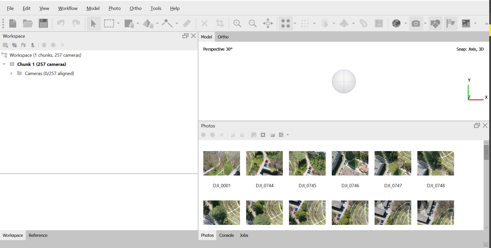 Figure 1: Image import
2) Align the images and calculate the low resolution point cloud :
Under Workflow/Align Photos, the parameters have been set like in Figure 2. Then, the operation has been launched by clicking ok. This takes approximatively 20 minutes to run. This operation aim to calculate the drone position where each picture has been taken, to align them and create a low resolution point cloud (Figure 3).
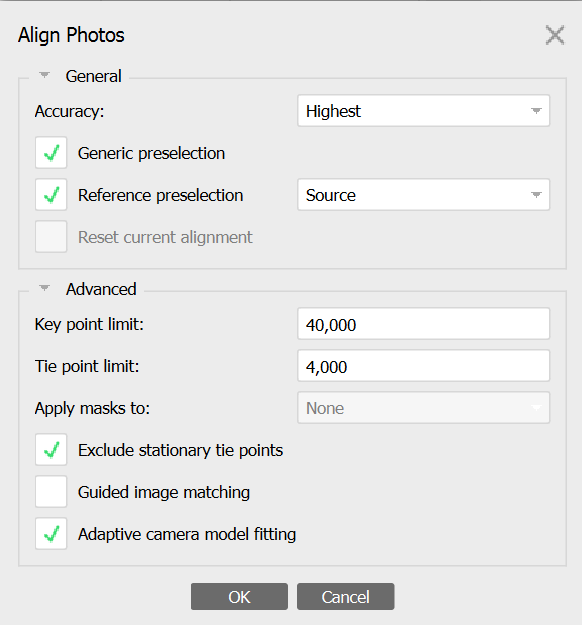 Figure 2: Alignment parameters
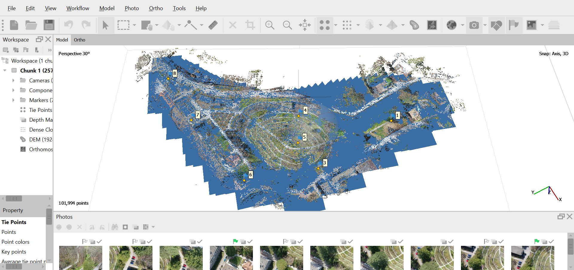 Figure 3: Tie points cloud model
3) Filter the tie points cloud model : dendron-dbgi\vassets\images\alignement_parameters.png
Some points in the points cloud could be wrong aligned. To obtain a high quality map, we have to remove them. Under Model/Gradual Selection we select Reconstruction Ucertainty and place the cursor at 10%. Then we ckick ok and delete (Figure 4). Then we repeat the operation with Project Accuracy. Then we have to update the camera positions in Tools/Optimize Cameras by ckicking ok.
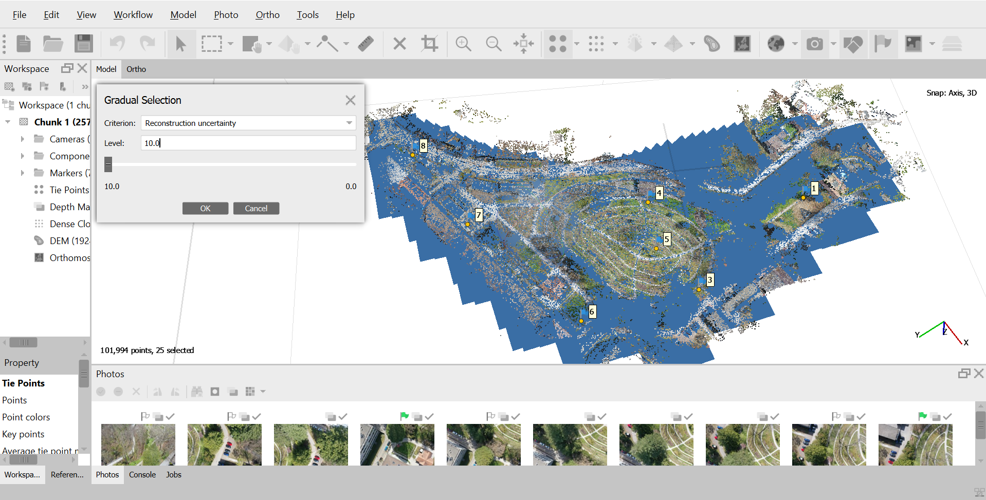 Figure 4: Gradual selection of the bad aligned points
4) Georeferencing :
Now we will import the ground control points to geolocate the map. You can find the ground control points coordinates of the Jardin botanique de l'université de Fribourg map here. To do that, we have to put them in a .txt file in the Reference/Import Reference tab. Then we put the settings displayed in Figure 5, then click ok and yes to all to create new control points. Then, in Reference settings we add the precision that is 2 centimeters under Marker accuracy (m).
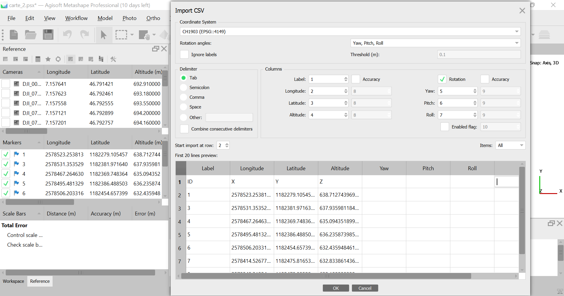 Figure 5: Importation of control points
Now we have to add these points on the pictures. To do that, we double click on a miniature in the photos tab under the tie points map and zoom on the control point. Then right click on the middle of the ground control point (more precise it is done, better the map will be), Place Marker/number of the control point (Figure 6). There is no need to select all the control points on each image, but we have to put each control point on 4 to 6 different pictures minimum. When it's done, we have to click the Update transform to save the control points position (little rounded arrows in front of the Reference tab).
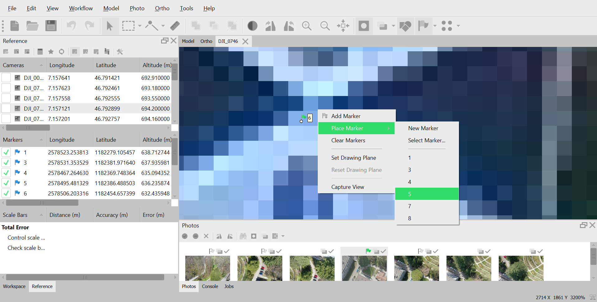 Figure 6: Placing the points on the images
5) Creation of the dense points cloud :
Now we have to create the dense points cloud. We go to Workflow/Build Dense Cloud with quality high. This step can take a very long time, approximatively 30 hours with a normal laptop.
6) Exportation of the orthophoto map
To export the map we go to Workflow/Build Othomosaic with 0.0136m pro pixel (Figure 7), that is the common space between points of the dense points cloud (after measurement with the Ruler on the dense cloud). We can then run the build of the orhtomosaic clicking ok. When it's done, we can export it going in the Workspace, right click on the Orthomosaic/Export Orthomosaic. Select the TIFF/GeoTIFF(*.tif) type. The map is done !
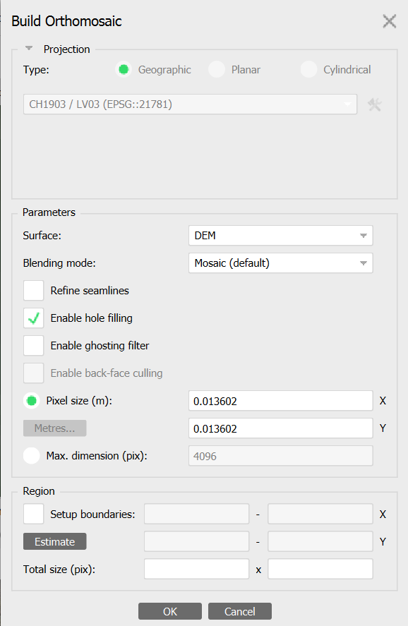 Figure 7: Settings to build the orthomosaic